|
|
|
 |
|
|
|
|
|
|
|
|
|
 |
|
|
|
|
|
|
|
|
|
|
|
|
| STEPPING
MOTOR CONTROL |
 |
|
|
|
|
|
|
|
|
|
|
|
|
|
|
|
|
|
|
|
|
 |
|
|
|
|
|
|
|
|
|
|
|
|
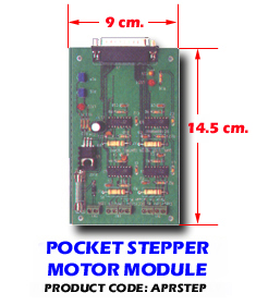
The dual stepping motor board is
used to drive stepping motor, and provides two stepping motor control
circuit. To drive the stepping motor, user can connect pocket 16 DO box
to dual stepping motor board, then connect stepping motor to it. The
pocket 16 DO box in no need to occupy any slot of your PC system, it is
suitable for any PC that contains a parallel printer port. Each
stepping motor controller provides four output signals and receives six
bits control string to drive stepping motor.
Features Pocket
Motor Control Module
*Support two
stepping motor control circuit.
*Voltage range: 14 to 28 V
*Maximum current : 1A
*The stepping motor is driven by pocket 16 DO box which is connected to
parallel print port.
*Support half step and full step revolution.
Hardware
Connections
|
|
|
|
|
|
 |
|
|
|
|
|
|
|
|
|
| Hardware Configuration |
Before you
use the dual stepper motor board, you must ensure that the power and
signal are set correctly. The proper settings for the dual stepper
motor board are described in the following. |
|
|
|
|
|
|
|
| TB1 |
 |
|
|
|
|
|
|
|
|
|
|
|
|
|
| The TB is use to connect the
control signal of stepper motor, it will rotate clockwise if the
connection is correct, otherwise, it will rotate counterclockwise or
shaking. Please connect correctly. |
TB2
|
 |
|
|
|
|
|
|
|
|
|
|
|
|
|
|
|
|
|
|
|
|
|
|
|
|
|
|
|
| The TB2 is used to connect the
control signal of stepper motor, it will rotate clockwise if connection
is correct, otherwise it will rotate counterclockwise of shaking.
Please connect it correctly |
|
|
|
| TB3
|
 |
|
|
|
|
|
|
|
|
|
|
|
|
|
|
|
|
|
|
|
|
|
|
|
|
 |
|
|
|
|
 |
|
|
|
|
|
|
|
|
|
|
|
|
|
|
|
|