
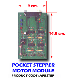
INTRODUCTION
The dual stepping motor board is used to drive stepping motor, and provides two stepping motors control circuit. To drive the stepping motor, user can connect Pocket 16 DO box to dual stepping motor board, then connect stepping motor to it. The pocket 16 DO box is no need to occupy any slot of your PC system, it is suitable for any PC that contains a parallel printer port. Each stepping motor controller provides four output signals and receives six bits control string to drive stepping motor.
The features of the dual stepping motor board are:
*Support two
stepping motor control circuit.
*Voltage range: 14 to 28V.
*Maximum current: 1 A.
*The stepping motor is driven by pocket 16 DO box which is connected to
parallel print port.
*Support half step and full step revolution.
*Operating temperature 0 to 60 oC.
*Storage temperature ¡V20 to 70 degree oC.
*Humidity 5% to 95% in non-condensing.
The package contains:
*Dual stepping
motor board.
*User¡¦s manual.
*Pocket 16 DO box and manual (optional).
Your dual stepping motor board is designed to be inserted to the pocket 16 DO box, please follow the steps listed below:
1.Turn off all power
to your computer and all peripheral devices before installing your dual
stepping motor board.
2.Connect pocket 16 DO box to printer port, then plug in power adapter
to pocket 16 DO box.
3.Connect dual stepping motor board to pocket 16 DO box, then plug in
power to stepping motor board.
4.Connect stepping motor to dual stepping motor board.
5.Turn on the computer and power adapter.
HARDWARE CONFIGURATIONS
Before you use the dual stepping motor board, you must ensure that the power and signal are set correctly. The proper settings for the dual stepping motor board are described in the following:
3.1 TB1
|
The TB1 is used to connect the control signal of stepping motor, it will rotate clockwise if connect is correct, otherwise it will rotate counterclockwise or shaking. Please connect it correctly. 3.2 TB2 |
|
The TB1 is used to connect the control signal of stepping motor, it will rotate clockwise if connect is correct, otherwise it will rotate counterclockwise or shaking. Please connect it correctly. 3.3 TB3(POWER)
|
| Pin | Description | Pin | Description |
| 1 | GND | 14 | +5V |
| 2 | DO10 |
15 | GND |
| 3 | DO11 |
16 | GND |
| 4 | DO12 |
17 | GND |
| 5 | DO13 |
18 | GND |
| 6 | DO14 |
19 | GND |
| 7 | DO15 |
20 | DO23 |
| 8 | DO16 |
21 | DO24 |
| 9 | DO17 |
22 | DO25 |
| 10 | DO20 | 23 | DO26 |
| 11 | DO21 | 24 | DO27 |
| 12 | DO22 | 25 | +5V |
| 13 | GND |
SOFTWARE PROGRAMMING
In the distribution diskette, we provide C, PASCAL, ASSEMBLY, and BASIC examples to show how to write software to control stepping motor. It is easy to run under MS/DOS or Windows environment.
4.1 Control Signal
The DO10 to DO17 are used to control stepping motor that was connected to TB1. The DO20 to DO27 are used to control stepping motor that was connected to TB2.
4.2 Software Programming
There are half step and full step control string to control stepping motor. To control stepping motor, please follow the control sequence that specifies in the below, and repeat output these control sequences from pocket 16DO box.
The control
sequence of half method are:
|
|
DO17
|
DO16
|
DO15
|
DO14
|
DO13
|
DO12
|
DO11
|
DO10
|
|
|
DO27
|
DO26
|
DO25
|
DO24
|
DO23
|
DO22
|
DO21
|
DO20
|
|
1
|
0
|
0
|
1
|
1
|
0
|
1
|
1
|
1
|
|
2
|
0
|
0
|
1
|
1
|
0
|
1
|
1
|
0
|
|
3
|
0
|
0
|
1
|
0
|
1
|
1
|
1
|
0
|
|
4
|
0
|
0
|
1
|
0
|
0
|
1
|
1
|
0
|
|
5
|
0
|
0
|
1
|
0
|
0
|
1
|
0
|
1
|
|
6
|
0
|
0
|
1
|
0
|
0
|
1
|
0
|
0
|
|
7
|
0
|
0
|
1
|
1
|
1
|
1
|
0
|
0
|
|
8
|
0
|
0
|
1
|
1
|
0
|
1
|
0
|
0
|
The control sequence of full step method are:
|
|
DO17
|
DO16
|
DO15
|
DO14
|
DO13
|
DO12
|
DO11
|
DO10
|
|
|
DO27
|
DO26
|
DO25
|
DO24
|
DO23
|
DO22
|
DO21
|
DO20
|
|
1
|
0
|
0
|
0
|
0
|
0
|
0
|
0
|
0
|
|
2
|
0
|
0
|
0
|
0
|
0
|
0
|
1
|
0
|
|
3
|
0
|
0
|
0
|
1
|
0
|
0
|
1
|
0
|
|
4
|
0
|
0
|
0
|
1
|
0
|
0
|
0
|
0
|
