The 16 channels
photo isolator input board for pocket 16 DI provides photo isolator
input functions, which allow the input signals to be completely floated
and prevent the ground loop.
Feature of 16
Channels Photo Isolator input Board
*Support 16 photo couple input channels.
*Breakdown voltage : AC/DC 500V minimum
*Allow the photo input signals to be completely floated and prevent the
ground loops.
*Input current : 80mA maximum for each isolated input.
*Input voltage : 15V DC maximum for each isolated input.
*LED indicates when corresponds channels is activated
*Isolated or non-isolated modes selectable.
Hardware
Connections
Hardware
Configurations
Before using the terminal board, you must be sure to have this board
plugged into 8255 card.
The LED17 in terminal board shows the power on status. When it light ups, it indicates that there is a power applied on the board, otherwise, when not lit, there is no power provided.
The jumpers are used to select isolated or non-isolated mode, when open the jumpers, it sets to isolated mode, otherwise when shorting the jumpers, it sets to non-isolated mode. JP1A and JP1b correspond to channel 0, JP2A and JP2B correspond to channel 1, etc. Whet set to non-isolated mode, the IxL is short to system ground. (where x is the channel number).Sample Program.
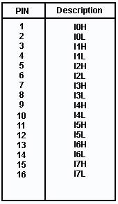
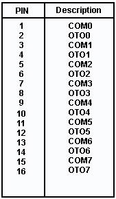
Pin Assignment of
TB1